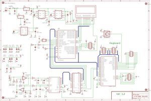
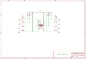
Народный осцилограф
оригинальный сайт http://www.eosystems.ro/eoscope/eoscope_en.htm
память возможна замена IDT7201 Медиа:IDT7200-IDT7201-IDT7202_DS.pdf на cy7c425 Медиа:cy7c419.pdf
индикатор возможна замена на WB240128D-YGH-TE_P Медиа:WB240128D_YGH_TE_P.pdf
операционик OPA2652 Медиа:opa2652.pdf
отрицаловка ICL7660 Медиа:ICL7660-MAX1044.pdf
АЦП ADS830 Медиа:ADS830.pdf
В Митраконе за 1587 руб, но в московском офисе http://www.mitracon.ru/ так-же он есть в Элитане за 1600 они высылают.
WB240128D-YGH-TE_P Даже часть элементов схемы не потредовалось, например источник отрицательного напряжения для ЖКИ, в этом дисплее он есть и есть место под резюк контраста.
Код для плисины
<source lang="vhdl">
-- Name: Scope Controller
-- Version: 1.4 Partially Tested
-- Date: 06Sep2005 Adi
-- Function: XC9572 controller for eOscope
--
-- Descrition:
-- Keyboard interface, ADC control logic
library IEEE;
use IEEE.STD_LOGIC_1164.ALL;
use IEEE.STD_LOGIC_ARITH.ALL;
use IEEE.STD_LOGIC_UNSIGNED.ALL;
entity controller is
 Port ( CLK :       in  std_logic;					-- Global Clock In
        UC_CLK :    out std_logic;					-- Output Clock for the uC
        ADC_CLK :   out std_logic;					-- Output Clock for the ADC
        FIFO_CLK :  out std_logic;					-- Output Clock for the FIFO
        TST_LED :   out std_logic;					-- Pin LED For testing purposes
DIN_SV5 : in std_logic_vector(7 downto 0); -- Keyboard data input
        SER_CLK :    in  std_logic;					-- Serial interface clock
        SER_DATA :   inout std_logic;					-- Serial interface - data !!!!! inout
        SER_EN :     in  std_logic;					-- Serial interface - Enable write in register
        SER_RDWR :   in  std_logic;					-- Serial interface - read or write
        SER_GATE :   in  std_logic						-- Serial interface - register select
);
-- attribute bufg: string; -- Global pin assign (FOR XC9572 - PC44) -- attribute bufg of CLK : signal is "CLK";
 attribute pin_assign : string;						-- Pin Assign (FOR XC9572 - PC44)
 attribute pin_assign of CLK :       signal is "6";
 attribute pin_assign of UC_CLK :    signal is "19";
 attribute pin_assign of FIFO_CLK :  signal is "29";
 attribute pin_assign of ADC_CLK :   signal is "28";
 attribute pin_assign of TST_LED :   signal is "1";
 attribute pin_assign of DIN_SV5 :   signal is "40, 39, 38, 37, 36, 35, 34, 33";
 		-- Pin connector SV5: 8, 7, 6, 5, 3, 2, 1
-- TrgDwn,
 attribute pin_assign of SER_CLK :    signal is "18";		-- uC: PC0
 attribute pin_assign of SER_RDWR:    signal is "20";		-- uC: PC1
 attribute pin_assign of SER_EN :     signal is "25";		-- uC: PC2
 attribute pin_assign of SER_DATA :   signal is "22";		-- uC: PD7
 attribute pin_assign of SER_GATE :   signal is "24";		-- uC: PD6 !!! Atentie !
end controller;
architecture Behavioral of controller is
signal CNT_1 : std_logic_vector(7 downto 0) := "00000000"; -- 8 bit counter (prescaller)
signal CNT_2 : std_logic_vector(15 downto 0) := "0000000000000000"; -- 16 bit counter (comparator)
signal OUT_CNT_1 : std_logic := '0';
signal OUT_CNT_2 : std_logic := '0';
signal OUT_TMP : std_logic := '0';
signal REG_DIV : std_logic_vector(3 downto 0) := "0000"; -- contains the division control data
signal REG_CMP : std_logic_vector(15 downto 0) := "0000000000000000"; -- contains the compare control data
signal REG_KEY : std_logic_vector(7 downto 0) := "00000000"; -- contains the key values
signal SER_DATA_TMP: std_logic := '0';
begin
 UC_CLK  <= CNT_1(1);									-- !!!!!!!!!!!! XTAL dependent
 ADC_CLK <=  not (CLK and SER_GATE) when REG_DIV = 7 else not (OUT_CNT_2 and SER_GATE);
 TST_LED <= CNT_1(7);									-- No LED drive, only for scope visualisation
 FIFO_CLK  <= (CLK and SER_GATE) when REG_DIV = 7 else (OUT_CNT_2 and SER_GATE);
 SER_DATA <= SER_DATA_TMP when SER_RDWR = '0' and SER_EN = '0' else 'Z';
 OUT_CNT_1 <= CLK when REG_DIV = 0 else OUT_TMP;
process (CLK, SER_CLK, SER_EN, SER_RDWR, DIN_SV5, SER_DATA, REG_DIV, REG_CMP, OUT_CNT_1, CNT_2)
-- Should be modified according to decision logic
begin
 if rising_edge(CLK) then                  -- Clock
   CNT_1 <= CNT_1 + '1';
   if REG_DIV = 1 then				    -- Must be reevaluated everytime the CLK changes !
     OUT_TMP <= CNT_1(0);
   elsif REG_DIV = 2 then
     OUT_TMP <= CNT_1(1);
   elsif REG_DIV = 3 then
     OUT_TMP <= CNT_1(2);
   elsif REG_DIV = 4 then
     OUT_TMP <= CNT_1(3);
   elsif REG_DIV = 5 then
     OUT_TMP <= CNT_1(4);
   elsif REG_DIV = 6 then
     OUT_TMP <= CNT_1(5);
   end if;
end if;
 if rising_edge(OUT_CNT_1) then
   if CNT_2 = REG_CMP then		  	     -- !!!! Not a 50% duty factor signal - I hope it works :)
     CNT_2 <= "0000000000000000";		-- (the 1 pulse is valid only for the CNT_2 reset period)
     OUT_CNT_2 <= '1';
   else
     CNT_2 <= CNT_2 + '1';				-- Increment the second counter
     OUT_CNT_2 <= '0';
   end if;
 end if;
 if SER_EN='1' then                        -- Serial transmission disabled - SER_CLK ignored
   REG_KEY <= DIN_SV5;
 elsif falling_edge(SER_CLK) then
   if SER_RDWR='0' then                    -- Read data from keyboard
SER_DATA_TMP <= REG_KEY(7);
     REG_KEY (7) <= REG_KEY (6);
     REG_KEY (6) <= REG_KEY (5);
     REG_KEY (5) <= REG_KEY (4);
     REG_KEY (4) <= REG_KEY (3);
     REG_KEY (3) <= REG_KEY (2);
     REG_KEY (2) <= REG_KEY (1);
     REG_KEY (1) <= REG_KEY (0);
     REG_KEY (0) <= '0';
   else                                    -- Write data to TimeBase settings registers
     REG_DIV (3) <= REG_DIV (2);
     REG_DIV (2) <= REG_DIV (1);
     REG_DIV (1) <= REG_DIV (0);
     REG_DIV (0) <= REG_CMP (15);
     REG_CMP (15) <= REG_CMP (14);
     REG_CMP (14) <= REG_CMP (13);
     REG_CMP (13) <= REG_CMP (12);
     REG_CMP (12) <= REG_CMP (11);
     REG_CMP (11) <= REG_CMP (10);
     REG_CMP (10) <= REG_CMP (9);
     REG_CMP (9) <= REG_CMP (8);
     REG_CMP (8) <= REG_CMP (7);
     REG_CMP (7) <= REG_CMP (6);
     REG_CMP (6) <= REG_CMP (5);
     REG_CMP (5) <= REG_CMP (4);
     REG_CMP (4) <= REG_CMP (3);
     REG_CMP (3) <= REG_CMP (2);
     REG_CMP (2) <= REG_CMP (1);
     REG_CMP (1) <= REG_CMP (0);
     REG_CMP (0) <= SER_DATA;
   end if;
 end if;
end process;
end Behavioral;
</source>

