Перевод статьи "Просто о ПИД-алгоритмах"
Автор: Tim Wescott
Перевод начал: Ботов Антон aka =DeaD=
Содержание
Введение
Алгоритмы ПИД (PID = proportional, integral, derivative) управления не так сложны, как кажется некоторым с первого взгляда. В этой статье мы попробуем рассказать как они работают на нескольких простых примерах. Изучив эти примеры, вы сможете самостоятельно применять эти алгоритмы в своих проектах.
Моя профессиональная деятельность непосредственно связана с реализацией управляющих циклов в программном обеспечении для различных устройств. Исходя из накопленного опыта, могу сказать, что не смотря на огромное количество алгоритмов и методов управления, которыми я владею - большая часть проблем такого сорта решается простейшими контроллерами без привлечения полного аппарата теории управления. В этой статье я расскажу, как реализовать и настроить простейший контроллер использующий ПИД-алгоритм без привлечения сложного математического аппарата и длительного изучения теории управления. Приведенная в статье техника настройки контроллера является проверенным и зарекомендовавшим себя методом, который можно успешно применять на большинстве задач управления.
ПИД управление
PID=ПИД означает "proportional=пропорциональный", "integral=интегральный", "derivative=дифференциальный". Эти три термина описывают простейшие элементы ПИД-контроллера. Каждый из этих элементов выполняет свою задачу и оказывает свое специфическое воздействие на функционирование системы.
В типичном ПИД-контроллере эти элементы оперируют комбинацией как входных управляющих параметров, так и сигналами обратной связи с управляемого устройства (объекта управления, далее просто - устройство). Выходы этих элементов складываются между собой и формируют управляющий сигнал для устройства.
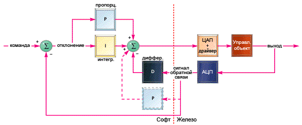
Рисунок 1. Простейший ПИД-контроллер
В приведенном на рисунке примере дифференциальный элемент оперирует только
сигналом обратной связи от устройства. Этот сигнал вычитается из сигнала
управляющего воздействия и полученная разность считается ошибкой управления.
Эта разность подается на вход пропорциональному и интегральным элементам,
получающиеся на их выходах сигналы складываются между собой и формируют
управляющий сигнал. Я не описывал принцип работы этих элементов - мы вернемся
к этому чуть позже. На схеме я указал альтернативный вариант включения
пропорционального элемента (пунктиром) - оптимальную схему включения можно
выбрать только на конкретном устройстве и задаче управления.
Объекты управления
Чтобы в обсуждении темы не уходить далеко от реальных задач нам понадобятся типичные объекты управления. В этой статье я буду использовать для примеров следующие три устройства, и покажу как на них будут работать те или иные алгоритмы ПИД-управления:
- Двигатель с редуктором;
- Безконтактная система сверхточного позиционирования;
- Термосистема;
Каждая из этих систем имеет различные характеристики и требует различных подходов в управлении для достижения оптимальных результатов.
Двигатель с редуктором
Первым рассмотрим двигатель с редуктором, на выходном валу которого установлен потенциометр или любым другим датчиком положения вала. Такое решение применяется в устройствах позиционирования печатной головки в струйных принтерах, или в системе управления дроссельной заглушкой в автомобильной системе круиз-контроля (поддержание заданной скорости на трассе), или в любой другой современной системе управления точным позиционированием.
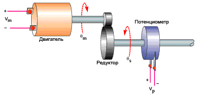
Рисунок 2. Схема управления двигателем с редуктором
Двигатель управляется уровнем напряжения задаваемым управляющим алгоритмом.
Усилие через редуктор поступает на его выходной вал и приводит в действие
некоторый механизм. На выходном валу находится потенциометр, через который
алгоритм управления получает информацию о положении выходного вала.
Коллекторный двигатель постоянного тока вращается с постоянной скоростью пропорциональной поданному напряжению. Реальный двигатель с редуктором не могут мгновенное изменять скорость вращения, поэтому между подачей на двигатель напряжения и установлением соответствующей скорости существует некоторая задержка. Редуктор в этой схеме просто умножает скорость вращения двигателя на некоторую константу.
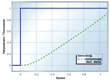
Рисунок 3. График положения вала при старте
На рисунке показано поведение системы при подаче некоторого фиксированого
напряжения в момент времени t = 0 (мы рассматриваем общие примеры, поэтому
примем напряжение в 1). Из графика видно, что мотор не сразу набирает
соответствующую напряжению скорость, но после того, как набрал (при t=0.2),
дальше он её поддерживает.
Безконтактная система сверхточного позиционирования
В некоторых случаях необходимо с сверхвысокой точностью управлять положением некоторого объекта. Систему, решающую эту задачу, можно построить из свободно перемещающейся механической платформы, пары "катушка + магнит" (аналогичной применяющимся в громкоговорителях) и безконтактного датчика положения. Такие решения применяются в механизмах оптической стабилизации в фото/видеотехнике, или в других системах, где нужно с высокой точностью перемещать небольшой элемент устройства.
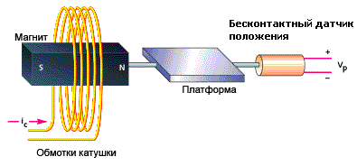
Рисунок 4. Безконтактная система сверхточного позиционирования
Программное обеспечение управляет подачей тока на обмотки катушки, который
создает магнитное поле соответствующей плотности и направления, которое
втягивает или выталкивает магнит вместе с платформой, на которой он закреплен.
Обратную связь по положению платформы обеспечивает безконтактный датчик.
При таком устройстве сила, прикладываемая к магниту не зависит от положения платформы и её движения. Плюс этого в том, что платформа ни от каких других воздействий не движется относительно всего устройства, а минус в том, что платформа становится очень неустойчивой, что затрудняет задачу управления. В добавок к этом нам окажется необходим усилитель с большим выходным током и высокоточный безконтактный датчик, что тоже может создать дополнительные трудности в проекте. Создание качественной и надежной системы такого типа достаточно проблемно без применения высокоточного оборудования и тщательного проектирования.
Уравнения, описывающие движение такой системы достоточно просты. Сила, действующая на платформу пропорциональна только уровню напряженности магнитного поля, а значит силе тока, протекающего через катушку. Таким образом ускорение платформы прямо пропорционально управляющему воздействию. График движения платформы при подаче фиксированного ненулевого управляющего воздействия это парабола:
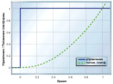
Рисунок 5. График движения при фиксированном воздействии
Как мы увидим позже - такое поведение платформы создаст дополнительные проблемы,
ввиду инертности, из-за которой она не сразу начинает двигаться, а также
стремится продолжить начатое движение.
Термосистема
В этом примере вместо двигателя мы будем использовать нагреватель.
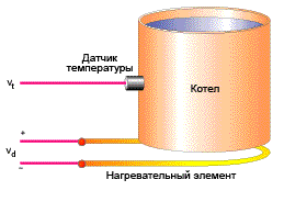
Рисунок 6. Типичная термосистема
Котел снабжен электрическим нагревателем, температура содержимого котла отслеживается с помощью соответствующего датчика температуры.
Вообще математические модели термосистем достаточно сложны, однако в нашем примере мы примем значительно упрощенную модель поведения такой системы. В той части случаев, когда вам не нужно получить выдающихся результатов обычно можно пользоваться менее точными моделями.
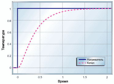
Рисунок 7. График поведения термосистемы при нагреве котла
Рисунок 7 показывает зависимость поведения системы от изменения Vd. Я использовать константы времени t1 = 0.1с и t2 = 0.3с. Как видно в итоге система приходит к требуемому состоянию, но это занимает очень много времени. Кроме того, без значительной теплоизоляции термосистемы очень чуствительны к внешнему воздействию. Этот эффект не показан в приведенном примере, но мы в этой статье позже рассмотрим его подробней.
Контроллеры
Элементы представляемого здесь ПИД-контроллера получают вход либо с датчика состояния управляемой системы, либо с датчика отклонения состояния системы от требуемого. Я буду писать код управляющего контроллера используя арифметику с плавающей точкой, чтобы не отвлекаться в этой статье на вопросы технической реализации, если вам нужно - вы можете легко адаптировать все приведенные здесь примеры к арифметике с фиксированной точкой.
Я буду предполагать, что всё функция управления будет определена нижеуказанным способом. По мере продвижения по тексту статьи вы увидите, как будет вырисовываться содержимое передаваемой структуры данных и внутренности функции.
<source lang="c"> double UpdatePID(SPid * pid,
double error, double position)
{
 .
 .
 .
} </source>
Причина по которой я передаю в процедуру управления отклонение от целевого состояния, а не состояние системы заключается в том, что иногда нам будет полезно как-то "поиграть" с этим параметром. Поэтому оставление рассчета отклонения в основном коде, вне нашей функции, делает нашу функцию более универсальной. В коде эта функция может быть использована, например, так:
<source lang="c">
 .
 .
 position = ReadPlantADC();
 drive = UpdatePID(&plantPID,
   plantCommand - position,
   position);
 DrivePlantDAC(drive);
 .
 .
</source>
Пропорциональное
Пропорциональное управление является самым легким в реализации и наиболее часто используется в управляющих циклах. Пропорциональный контроллер просто берет отклонение, умножает его на константу и выдает его в качестве управляющего воздействия. Пропорциональный компонент в контроллере рассчитывается кодом следующего вида:
<source lang="c">
 double pTerm;
 .
 .
 .
 pTerm = pid->pGain * error;
 .
 .
 .
 return pTerm;
</source>
Figure 8 shows what happens when you add proportional feedback to the motor and gear system. For small gains (kp = 1) the motor goes to the correct target, but it does so quite slowly. Increasing the gain (kp = 2) speeds up the response to a point. Beyond that point (kp = 5, kp = 10) the motor starts out faster, but it overshoots the target. In the end the system doesn't settle out any quicker than it would have with lower gain, but there is more overshoot. If we kept increasing the gain we would eventually reach a point where the system just oscillated around the target and never settled out-the system would be unstable.
The motor and gear start to overshoot with high gains because of the delay in the motor response. If you look back at Figure 2, you can see that the motor position doesn't start ramping up immediately. This delay, plus high feedback gain, is what causes the overshoot seen in Figure 8. Figure 9 shows the response of the precision actuator with proportional feedback only. Proportional control alone obviously doesn't help this system. There is so much delay in the plant that no matter how low the gain is, the system will oscillate. As the gain is increased, the frequency of the output will increase but the system just won't settle.
Figure 10 shows what happens when you use pure proportional feedback with the temperature controller. I'm showing the system response with a disturbance due to a change in ambient temperature at t = 2s. Even without the disturbance you can see that proportional control doesn't get the temperature to the desired setting. Increasing the gain helps, but even with kp = 10 the output is still below target, and you are starting to see a strong overshoot that continues to travel back and forth (this is called ringing).
As the previous examples show, a proportional controller alone can be useful for some things, but it doesn't always help. Plants that have too much delay, like the precision actuator, can't be stabilized with proportional control. Some plants, like the temperature controller, cannot be brought to the desired set point. Plants like the motor and gear combination may work, but they may need to be driven faster than is possible with proportional control alone. To solve these control problems you need to add integral or differential control or both.
Integral
Integral control is used to add long-term precision to a control loop. It is almost always used in conjunction with proportional control.
The code to implement an integrator is shown below. The integrator state, iState is the sum of all the preceding inputs. The parameters iMin and iMax are the minimum and maximum allowable integrator state values.
<source lang="c"> double iTerm;
 .
 .
 .
// calculate the integral state // with appropriate limiting
 pid->iState += error;
 if (pid->iState > pid->iMax)
   pid->iState =
pid->iMax;
 else if (pid->iState
<
pid->
   iMin)
   pid->iState = pid->iMin;
 iTerm = pid->iGain * iState;
  // calculate the integral term
 .
 .
 .
</source>
Integral control by itself usually decreases stability, or destroys it altogether. Figure 11 shows the motor and gear with pure integral control (pGain = 0). The system doesn't settle. Like the precision actuator with proportional control, the motor and gear system with integral control alone will oscillate with bigger and bigger swings until something hits a limit. (Hopefully the limit isn't breakable.)
Figure 12 shows the temperature control system with pure integral control. This system takes a lot longer to settle out than the same plant with proportional control (see Figure 10), but notice that when it does settle out, it settles out to the target value-even with the disturbance added in. If your problem at hand doesn't require fast settling, this might be a workable system.
Figure 12 shows why we use an integral term. The integrator state "remembers" all that has gone on before, which is what allows the controller to cancel out any long term errors in the output. This same memory also contributes to instability-the controller is always responding too late, after the plant has gotten up speed. To stabilize the two previous systems, you need a little bit of their present value, which you get from a proportional term.
Figure 13 shows the motor and gear with proportional and integral (PI) control. Compare this with Figures 8 and 11. The position takes longer to settle out than the system with pure proportional control, but it will not settle to the wrong spot.
Figure 14 shows what happens when you use PI control on the heater system. The heater still settles out to the exact target temperature, as with pure integral control (see Figure 12), but with PI control, it settles out two to three times faster. This figure shows operation pretty close to the limit of the speed attainable using PI control with this plant.
Before we leave the discussion of integrators, there are two more things I need to point out. First, since you are adding up the error over time, the sampling time that you are running becomes important. Second, you need to pay attention to the range of your integrator to avoid windup.
The rate that the integrator state changes is equal to the average error multiplied by the integrator gain multiplied by the sampling rate. Because the integrator tends to smooth things out over the long term you can get away with a somewhat uneven sampling rate, but it needs to average out to a constant value. At worst, your sampling rate should vary by no more than ?ver any 10-sample interval. You can even get away with missing a few samples as long as your average sample rate stays within bounds. Nonetheless, for a PI controller I prefer to have a system where each sample falls within ? ? the correct sample time, and a long-term average rate that is right on the button.
If you have a controller that needs to push the plant hard, your controller output will spend significant amounts of time outside the bounds of what your drive can actually accept. This condition is called saturation. If you use a PI controller, then all the time spent in saturation can cause the integrator state to grow (wind up) to very large values. When the plant reaches the target, the integrator value is still very large, so the plant drives beyond the target while the integrator unwinds and the process reverses. This situation can get so bad that the system never settles out, but just slowly oscillates around the target position.
Figure 15 illustrates the effect of integrator windup. I used the motor/controller of Figure 13, and limited the motor drive to ?Not only is controller output much greater than the drive available to the motor, but the motor shows severe overshoot. The motor actually reaches its target at around five seconds, but it doesn't reverse direction until eight seconds, and doesn't settle out until 15 seconds have gone by.
The easiest and most direct way to deal with integrator windup is to limit the integrator state, as I showed in my previous code example. Figure 16 shows what happens when you take the system in Figure 15 and limit the integrator term to the available drive output. The controller output is still large (because of the proportional term), but the integrator doesn't wind up very far and the system starts settling out at five seconds, and finishes at around six seconds.
Note that with the code example above you must scale iMin and iMax whenever you change the integrator gain. Usually you can just set the integrator minimum and maximum so that the integrator output matches the drive minimum and maximum. If you know your disturbances will be small and you want quicker settling, you can limit the integrator further.
Differential
I didn't even show the precision actuator in the previous section. This is because the precision actuator cannot be stabilized with PI control. In general, if you can't stabilize a plant with proportional control, you can't stabilize it with PI control. We know that proportional control deals with the present behavior of the plant, and that integral control deals with the past behavior of the plant. If we had some element that predicts the plant behavior then this might be used to stabilize the plant. A differentiator will do the trick.
The code below shows the differential term of a PID controller. I prefer to use the actual plant position rather than the error because this makes for smoother transitions when the command value changes. The differential term itself is the last value of the position minus the current value of the position. This gives you a rough estimate of the velocity (delta position/sample time), which predicts where the position will be in a while.
<source lang="c"> double dTerm;
 .
 .
 .
dTerm = pid->dGain * (position - pid->dState);
 pid->dState = position;
 .
 .
 .
</source>
With differential control you can stabilize the precision actuator system. Figure 17 shows the response of the precision actuator system with proportional and derivative (PD) control. This system settles in less than 1/2 of a second, compared to multiple seconds for the other systems. Figure 18 shows the heating system with PID control. You can see the performance improvement to be had by using full PID control with this plant.
Differential control is very powerful, but it is also the most problematic of the control types presented here. The three problems that you are most likely going to experience are sampling irregularities, noise, and high frequency oscillations. When I presented the code for a differential element I mentioned that the output is proportional to the position change divided by the sample time. If the position is changing at a constant rate but your sample time varies from sample to sample, you will get noise on your differential term. Since the differential gain is usually high, this noise will be amplified a great deal.
When you use differential control you need to pay close attention to even sampling. I'd say that you want the sampling interval to be consistent to within 1% of the total at all times-the closer the better. If you can't set the hardware up to enforce the sampling interval, design your software to sample with very high priority. You don't have to actually execute the controller with such rigid precision-just make sure the actual ADC conversion happens at the right time. It may be best to put all your sampling in an ISR or very high-priority task, then execute the control code in a more relaxed manner.
Differential control suffers from noise problems because noise is usually spread relatively evenly across the frequency spectrum. Control commands and plant outputs, however, usually have most of their content at lower frequencies. Proportional control passes noise through unmolested. Integral control averages its input signal, which tends to kill noise. Differential control enhances high frequency signals, so it enhances noise. Look at the differential gains that I've set on the plants above, and think of what will happen if you have noise that makes each sample a little bit different. Multiply that little bit by a differential gain of 2,000 and think of what it means.
You can low-pass filter your differential output to reduce the noise, but this can severely affect its usefulness. The theory behind how to do this and how to determine if it will work is beyond the scope of this article. Probably the best that you can do about this problem is to look at how likely you are to see any noise, how much it will cost to get quiet inputs, and how badly you need the high performance that you get from differential control. Once you've worked this out, you can avoid differential control altogether, talk your hardware folks into getting you a lower noise input, or look for a control systems expert.
The full text of the PID controller code is shown in Listing 1 and is available at www.embedded.com/code.html.
Listing 1: PID controller code
<source lang="c"> typedef struct {
 double dState;      	// Last position input
 double iState;      	// Integrator state
 double iMax, iMin;
 // Maximum and minimum allowable integrator state
 double	iGain,    	// integral gain
       	pGain,    	// proportional gain
        	dGain;     	// derivative gain
} SPid; double UpdatePID(SPid * pid, double error, double position) {
 double pTerm,
dTerm, iTerm;
 pTerm = pid->pGain * error;
 // calculate the proportional term
// calculate the integral state with appropriate limiting
 pid->iState += error;
 if (pid->iState > pid->iMax) pid->iState = pid->iMax;
 else if (pid->iState
<
pid->iMin) pid->iState = pid->iMin;
 iTerm = pid->iGain * iState;  // calculate the integral term
 dTerm = pid->dGain * (position - pid->dState);
 pid->dState = position;
 return pTerm + iTerm - dTerm;
} </source>
Tuning
The nice thing about tuning a PID controller is that you don't need to have a good understanding of formal control theory to do a fairly good job of it. About 90% of the closed-loop controller applications in the world do very well indeed with a controller that is only tuned fairly well.
If you can, hook your system up to some test equipment, or write in some debug code to allow you to look at the appropriate variables. If your system is slow enough you can spit the appropriate variables out on a serial port and graph them with a spreadsheet. You want to be able to look at the drive output and the plant output. In addition, you want to be able to apply some sort of a square-wave signal to the command input of your system. It is fairly easy to write some test code that will generate a suitable test command. Once you get the setup ready, set all gains to zero. If you suspect that you will not need differential control (like the motor and gear example or the thermal system) then skip down to the section that discusses tuning the proportional gain. Otherwise start by adjusting your differential gain.
The way the controller is coded you cannot use differential control alone. Set your proportional gain to some small value (one or less). Check to see how the system works. If it oscillates with proportional gain you should be able to cure it with differential gain. Start with about 100 times more differential gain than proportional gain. Watch your drive signal. Now start increasing the differential gain until you see oscillation, excessive noise, or excessive (more than 50%) overshoot on the drive or plant output. Note that the oscillation from too much differential gain is much faster than the oscillation from not enough. I like to push the gain up until the system is on the verge of oscillation then back the gain off by a factor of two or four. Make sure the drive signal still looks good. At this point your system will probably be responding very sluggishly, so it's time to tune the proportional and integral gains.
If it isn't set already, set the proportional gain to a starting value between 1 and 100. Your system will probably either show terribly slow performance or it will oscillate. If you see oscillation, drop the proportional gain by factors of eight or 10 until the oscillation stops. If you don't see oscillation, increase the proportional gain by factors of eight or 10 until you start seeing oscillation or excessive overshoot. As with the differential controller, I usually tune right up to the point of too much overshoot then reduce the gain by a factor of two or four. Once you are close, fine tune the proportional gain by factors of two until you like what you see.
Once you have your proportional gain set, start increasing integral gain. Your starting values will probably be from 0.0001 to 0.01. Here again, you want to find the range of integral gain that gives you reasonably fast performance without too much overshoot and without being too close to oscillation.
Other issues
Unless you are working on a project with very critical performance parameters you can often get by with control gains that are within a factor of two of the "correct" value. This means that you can do all your "multiplies" with shifts. This can be very handy when you're working with a slow processor.
Sampling rate
So far I've only talked about sample rates in terms of how consistent they need to be, but I haven't told you how to decide ahead of time what the sample rate needs to be. If your sampling rate is too low you may not be able to achieve the performance you want, because of the added delay of the sampling. If your sampling rate is too high you will create problems with noise in your differentiator and overflow in your integrator.
The rule of thumb for digital control systems is that the sample time should be between 1/10th and 1/100th of the desired system settling time. System settling time is the amount of time from the moment the drive comes out of saturation until the control system has effectively settled out. If you look at Figure 16, the controller comes out of saturation at about 5.2s, and has settled out at around 6.2s. If you can live with the one second settling time you could get away with a sampling rate as low as 10Hz.
You should treat the sampling rate as a flexible quantity. Anything that might make the control problem more difficult would indicate that you should raise the sampling rate. Factors such as having a difficult plant to control, or needing differential control, or needing very precise control would all indicate raising the sampling rate. If you have a very easy control problem you could get away with lowering the sampling rate somewhat (I would hesitate to lengthen the sample time to more than one-fifth of the desired settling time). If you aren't using a differentiator and you are careful about using enough bits in your integrator you can get away with sampling rates 1,000 times faster than the intended settling time.
Exert control
This covers the basics of implementing and tuning PID controllers. With this information, you should be able to attack the next control problem that comes your way and get it under control.
Tim Wescott has a master's degree in electrical engineering and has been working in industry for more than a decade. His experience has included a number of control loops closed in software using 8- to 32-bit microprocessors, DSPs, assembly language, C, and C++. He is currently involved in control systems design at FLIR Systems where he specifies mechanical, electrical, and software requirements and does electrical and software design. You can contact him at tim@wescottdesign.com.